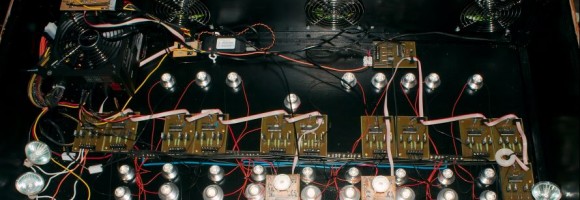
The hardware is finally in! This post is a geeky tech post as a result 😉 I had some issues soldering an SMT component that was not in stock at the PCB manufacturer… So I needed to solder that manually. After that the rest of the THT components were soldered, and then it was test, update software, test, update software.

Manually soldering a TSSOP28
As I quickly discovered – no fun. The Chinese PCB manufacturer mounted all SMT components, except one: The PCA9685 PWM timer which was out of stock.
So I ordered the chips separately and manually soldered the thing. Using a soldering iron and soldering flux I managed to get the component soldered. Up close it is REALLY ugly, but eh, it works:

After soldering that chip I mounted the first THT component so I could get testing. I mounted the Arduino Mega 2560 Pro board, the power connectors, some THT resistors and things like a single relay.
I powered on the board using a current-limited power supply. No dramatic currents were running so I took the change and hooked up the board to a heavy 5V, 12V and 24V power supply. The power leds came on and the board came to life!
It’s all about the software
In order to be able to test the hardware, I did need software… Luckily I already had the existing Paludarium (Paludarium 2017) software which is very much like the Artemis setup (only less ports and features). So I modified the software to match the new pin-out of inputs and outputs, and uploaded the code.
The Pulse Width Modulation (PWM) outputs used to dim 12V and 24V leds worked right out of the gate from the internal Arduino PWM ports. The manually soldered PCA9685 did not work yet as the Artemis board is different in that respect: There is an I2C channel switch between the Arduino and the PCA9685 (This is a PCA9546a 4 channel I2C switch). After fiddling around I got the I2C switch to pass the I2C signals to the PCA9685 and these PWM outputs started to live as well.

As I went along I tested more and more hardware. What is working right now:
- 31 PWM outputs in a mix of 12V and 24V;
- 4 Analog outputs (0-10V) for dimming TL lighting;
- 4 relays that switch 230VAC devices on and off;
- Analog inputs for LM35 temperature sensors, PH Sensor, conductivity sensor inputs;
- Extra I2C channels;
- Extra serial ports;
- 12V and 24V sense inputs (so the Arduino can measure presence of these);
- USB power outputs – OUCH! I managed to swap GND and +5V. Luckily this could be fixed by some creative soldering.
Things that remain to be tested:
- There is a port for a WS2812b intelligent led strip (NeoPixel). The port works, but I haven’t yet written the software to support the leds.
- External I2C humidity sensors. I simply have not written the software to support these yet.
- 230VAC voltage detect circuit. I simply did not get round to feeding 230VAC into the board plus there is no software (I should be able to measure the 50Hz duty cycle of the mains voltage).
With these results, I will not require to build a new version of the hardware; it is almost completely functional and things that did not work have workarounds.
What the software can do today
Actually the software is quite feature rich already; I use serial communications from a Raspberry Pi to talk to the Artemis. Using serial commands, the Artemis is already able to do quite impressive things:
- All PWM outputs can be programmed individually in 256/4096 steps;
- All PWM outputs can “walk” to their destination intensity all in individual speeds (you simply program a destination and a number of seconds Artemis should take to get there);
- All PWM and digital outputs can be programmed to be active for a number of seconds for things like pumps and mistmakers;
- All PWM outputs and digital outputs can individually be programmed to be inverted;
- Analog values can be read;
- Analog values can measure automatically (between 1-60 seconds per sample) and then compared to programmable values. Artemis can then actuate a PWM or digital output depending on the analog inputs. This is used to control things like heaters with temperature sensors.
- THUN-DER!!!! Just like a very old build I once did, thunder is back in all of its glory. This is the first time you can program thunder in a fully generic way: You first program participating PWM channels and their order. You then program the intensity and how fast the thunder should “roll” through the lights. Then you simply shoot a command to the Artemis to do either a FLASH or a ROLL of thunder and off it goes!

Quite a list already, right? Just some more debugging to do and maybe add some features like external I2C humidity sensor support, WS2812b led strip support and then the stuff is ready to go onto github so everyone can learn/use and abuse 🙂
Stay tuned for more!


 RSS
RSS LinkedIn
 Twitter
 Email
Email
[…] to the “C”. Today I still program in both “C” and Python for fun (Arduino and Raspberry Pi […]