Category Archives: Automation

The way of water: The WaterWorx

I get quite some questions regarding the water household in the new paludarium. When I try to explain, I was always like “wish I had a picture of this”. And now I do!

Introducing “The WaterWorx”

The WaterWorx is a compilation of all water management related things that drive the paludarium. It consists of pumps, valves, tubes, containers, level sensors and things like a reverse-osmosis unit. All of these things are controlled by Artemis, the embedded controller (that is actually Arduino based). The Raspberry Pi on top of Artemis also does some monitoring and higher-level controlling as well. To just drop you an image of the WaterWorx, here it is:

Part 1: Reverse osmosis unit

Read more »

Cloud-native ramblings: Adding Redis

Many people think I am “just” building a paludarium… But they don’t see the complex world of automation behind it. In fact, there is a full blown application running the paludarium, build in a limited-but-functional cloud-native architecture.

This architecture is limited… Because you can have multiple instances of your microservices… But in the end there is only one piece of hardware to control. A single relais, a single led light, a single pump, a single valve and a single level sensor. And this is a problem; what if multiple microservices all talk to the one hardware platform at the same time? I needed a way to put a lock on who can send commands, and Redis came to the rescue.

The limitations of having “one hardware”

What if you have all kinds of microservices and functions that all want to talk to a single hardware platform? There are several functions and services that want to talk to the hardware:

Read more »

Artemis hard- and software = WORKING!

After more testing, more writing code and more debugging I have finally managed to call the code inside the Artemis as COMPLETE. The last few bits and pieces came together, so next step will be to work on the higher level software inside the Raspberry Pi.

Artemis has been put through it paces. It all seems to work OK now, Although I did need to make some changes here and there…

Read more: Artemis hard- and software = WORKING!

NeoPixel Ledstrip: Working

So The “smart” led strips with the WS2812b smart leds on board refused to work initially. After a lot of debugging I figured out that the first NeoPixel, the onboard ws2812b was the culprit. It just would not work properly, even though it would pass the bitbanged stuff to the rest of the led strip in the correct way.

Read more »

Adding software features to Artemis

New things! Everything is progressing nicely. Did additional testing on the 230VAC detection circuit and wrote software to read SHT31 digital humidity/temperature sensors. Also added a ClosedLoop function so analog inputs can be used to compare to store values and have an outputs act on the comparison.

230VAC detection

Finally I had the time to properly measure the mains voltage inputs. No shorts or anything… So I decided to go on and plug in the mains voltage into the Artemis.

The 230VAC detection circuit is connected to D48 (ICP5 on the Arduino), which mean I could potentially measure the exact frequency of the mains AC voltage. Still, I do not require to have that, so instead I built a simple timer that resets if the phase comes up, and counts down if the phase disappears. This way I always have a stable reading on the signal, even when the Artemis accidentally measures on an exact phase zero crossing.

        if (digitalRead(PIN_230V_DETECT) == LOW) // Active? Reset Timer.
        {
                TIM_50HzDetect = 10;
        }
        else
        {
                if (TIM_50HzDetect) // Not active -> count 2 zero and stay.
                {
                        TIM_50HzDetect--;
                }
        }
Read more »

Putting Artemis through it paces

The hardware is finally in! This post is a geeky tech post as a result 😉 I had some issues soldering an SMT component that was not in stock at the PCB manufacturer… So I needed to solder that manually. After that the rest of the THT components were soldered, and then it was test, update software, test, update software.

Just like the computer render – but this time it is for real! The first prototype is just about ready to go!

Manually soldering a TSSOP28

As I quickly discovered – no fun. The Chinese PCB manufacturer mounted all SMT components, except one: The PCA9685 PWM timer which was out of stock.

So I ordered the chips separately and manually soldered the thing. Using a soldering iron and soldering flux I managed to get the component soldered. Up close it is REALLY ugly, but eh, it works:

Read more »

Artemis hardware ordered!

After looking at the schematic, looking over it again and once more, then at the PCB once more… I decided there could not be too much wrong with the design as-is… So I pulled the trigger and ordered five PCBs including SMT parts!

After Artemis v1.00 was almost sent to production I did make some last minute changes. That resulted in v1.01 of the hardware. Yesterday was a big day: I finally uploaded my design to jlcpcb.com and progressed with the order!

Exciting! The PCB or Artemis v1.01 finally went into production.
Read more »

Final tweaking to Artemis, the smart paludarium controller

Getting ready to have the main PCB built in China, I discovered some things that made me rethink… And make some pretty radical changes to the PCB… Enter v1.01!

Change 1: PWM for LEDs in high-res

The most major change “came to light” when I played with a prototype to control my new LED panel. Right now it uses PWM directly from the Arduino, so that is 256 steps (8 bit resolution).

But especially at lower light intensities I can see the LEDs take their steps. As I also have 16 channels controlled by a PCA9685 chip which is 12 bit resolution (so 4096 steps), I decided to use the PCA9685 outputs to run lighting. This in turn meant I needed to rethink which outputs work on 12V and which ones work on 24V. In the end I solved the puzzle and came up with a clean design:

Artemis v1.01: Changes to the layout of 12V and 24V power feeds and connectors. Note the large 6 pin connectors on the left: They are 24V RGB-CCT outputs now run from the PCA9685 PWM chip.
Read more »

Paludarium 2020: Electronics!

I admit… I have failed to post any new blogs on my current Paludarium setup. I posted the construction of the wooden cabinet… And then it stopped. I did however finish the build, and maybe I’ll add a post on that one later. In this post I introduce a new paludarium design, and it is getting ready to be actually build! It is going to be bigger, better, faster, more! ehhh… more automated than EVER.

The problem with these larger projects is that there are SO many bits and pieces to put together. Today I am writing up part one as I am almost ready to push the button on ordering a complete PCB that will contain practically all electronics required for my new Paludarium 2020 build!

Requirements for the electronics

I wanted to be sure I’d create a PCB that has all stuff on board I might be needing, without overdoing things. Still, I ended up with a huge amount of speeds and feeds. Here they are in random order:

Read more »

Sensirion SHT-11 humidity and temperature sensor ready to go!

One of the sensors that can be read by the Neptune module is the Sensirion SHT-11 I have had laying about for years.

Now finally it is ready for use! The sensor sits on the end of a 2,5 meter cable which is soldered on directly. A small capacitor is glued on as well to cope with the excessive cable length. The sensor in its entirety is covered in a drop of silicon glue to keep the moisture out of the electronic contacts. This sensor will be measuring over 98% relative humidity at times!

The Sensirion SHT-11 sensor glued into a drop of silicone. This digital sensor measures air temperature and relative humidity in the Paludarium.

The Sensirion SHT-11 sensor glued into a drop of silicone. This digital sensor measures air temperature and relative humidity in the Paludarium.

So far the results are looking good. This is the sensor still hanging in the living room:

sensirion

22.24 degrees centigrade and 65.94% relative humidity. Sounds realistic as it’s a very moist day.

When the silicone had dried, I put the sensor inside the paludarium. After settling it showed measurements like these:

Measured values when the Sensirion sensor is inside the Paludarium.

Measured values when the Sensirion sensor is inside the Paludarium.

Great! Tempereature at 23.16 degrees, relative humidity at 87,61%. Very Jungley 🙂

What I did find out, is that the location of the sensor heavily influences the measurements. Especially the humidity is VERY dependent on where you measure.

Neptune module taken into action

Finally. After a long time building the hardware and the software, the Neptune module is the final module to be added to the Paludarium.

This module is a more complex version of the Apollo units that live inside the Canopy that control lighting and fans. The Neptune module has some control for lighting (namely the underwater lights), but its main purpose is controlling pumps and valves, and measuring back sensors in the paludarium.

For now the Neptune module is setup in the cabinet under the Paludarium:

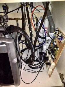
The Neptune module sitting in the cabinet under the Paludarium with some sensors already connected. What a mess of wires and hoses!

The Neptune module sitting in the cabinet under the Paludarium with some sensors already connected. What a mess of wires and hoses!

The unit has been running for over two weeks now without a single flaw… I must be doing something right 😉